

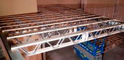
Posi-STRUT Truss System
Design Loads, Criteria and Durability
Design Loads
Refer also to NZS3604 and NZS4203. Posi-STRUT trusses supporting load-bearing walls are not covered by these charts and require special design.
Dead loads
| Heavy Roof Rafter | 0.60 kPa |
| Light Roof Rafter | 0.20 kPa |
| Light Roof Purlin | 0.15 kPa |
| Ceiling | 0.15 kPa |
| Floor (1.5, kPa LL) + ceiling | 0.4 kPa |
| Floor (2.5,3.0 kPa LL) + ceiling | 0.5 kPa |
Live loads
| Distr. | Conc. | |
| Roof, maintenance | 0.25 kPa | 1.0 kN |
| Floor, domestic | 1.5 kPa | 1.8 kN |
| Floor, office | 1.5 kPa | 2.7 kN |
| Floor, public use | 3.0 kPa | 2.7 kN |
Wind loads
Design Wind Speed | qu | |
| Low | 32 m/s | 0.61 kPa |
| Medium | 37 m/s | 0.82 kPa |
| High | 44 m/s | 1.16 kPa |
| Very High | 50 m/s | 1.5 kPa |
Combined pressure coefficients Cp = 1.2 max
Snow loads
0.5kPa and 1.0 kPa
Special design is required for higher design loads.
Deflection Criteria
Refer also to BRANZ guidelines.
Floors
| Span/360 | Maximum under live load only (for liveliness control) |
| Span/300 | or 24 mm maximum under permanent load (G+0.4Q, including creep) |
Rafters
| Span/360 | or 24 mm maximum under permanent load |
| Span/333 | under wind load (with ceiling) |
| Span/167 | under wind load (without ceiling) |
Purlins
| Span/240 | or 36mm maximum under dead and live load |
| Span/167 | under wind load |
Cantilevers
| Span/150 | or 8mm maximum under dead and live load |
Design Strength
Trusses are designed to the Limit State Design provisions of NZS4203 and NZS3603.
Timber stresses
Timber properties to NZS 3603 Table 2.3
F5 machine stress graded: fb = 16.2, ft = 8.1, fc = 12.1 MPa , E = 6.9GPa
F8 machine stress graded: fb = 25.4, ft = 12.7, fc = 19.5 MPa , E = 9.1GPaNo.1 Framing can be used in the place of F5 timber due to higher strengths, F5 charts may be used to select truss sizes required.
MGP10 timber may be substituted for F5, MGP12 timber may be substituted for F8.
Modification factors
Durability
This Section covers the durability of parallel chord Posi-STRUT floor trusses to support a light timber floor. Posi-STRUT webs are manufactured from 0.91mm ASTM A446 Grade A steel, with a Z275 galvanised coating. The webs are pressed into timber by accredited GANG-NAIL fabricators to form a parallel chord truss. GANG-NAIL toothed metal connectors (G300 steel with Z275 galvanised coating) are also used in the manufacture of the trusses to fix the timber members together.
Midfloor System
Posi-STRUT floor trusses used in midfloor situations are completely closed in and usually require no further protection to satisfy 50 year durability requirements.
Instructions on the Use of Charts
The selection charts are based on maximum span tables. All spans for rafters (and purlins) are measured along the slope, not horizontal spans. First determine the load condition for the truss, for example floor live load, or type of roof material, wind zone and snow zone.
Based on different truss spacings, the maximum spans for different truss sizes can be selected. Maximum truss spans for intermediate truss spacings may be obtained by interpolating between the published results. Extrapolation beyond maximum and minimum spacings is not permitted.
With snow loads, the wind zone category has to be determined as well in order to use the selection charts. For snow loads over 1.0 kPa, please contact the MiTek Design Office for assistance.
Example:
Domestic Floor: 1.5kPa Live Load, timber F5, Truss Spacing = 450mm. Required span = 5m
The correct truss type is the one whose maximum allowable span selected from the charts equals or exceeds the required span. Spans in bold and shaded indicate double webs for fabrication. It is important to write "DW" beside the truss code to indicate the double web requirement. A number of end support details possible with Posi-STRUT trusses and it is advisable to show the type required for your application. Several possible types of support details are shown in the Detailing Section of this Manual, which are by no means exhaustive. Consult MiTek Design Office if you looking for an alternative detail. Special web positions may be possible to incorporate ducting around mid-span. It is necessary to specify this requirement where duct sizes over 100mm diameter are anticipated. Details of fire rating and acoustic rating systems, which are derived from tests performed by and opinions provided by the Building Research Association of New Zealand, Winstone Wallboards Ltd and Marshall Day Associates, are included in section P13.
Floor Stiffness
The dynamic response of a floor system to foot traffic and other moving loads is dependant on many factors such as the floor plan of supported walls, applied load, furniture layout, dynamic response of the support structure, etc. The comfort and expectations of occupants also varies widely. Posi-STRUT floor trusses are designed to conform to the vibration requirements of the New Zealand Building Standard NZS4203. When selecting Posi-STRUT trusses consideration should be given to the springiness of the floor. Generally the floor stiffness provided by trusses selected from the tables and designed in MiTek AB meets the expectations of most occupants. In situations where the trusses are near their maximum span and there are no internal non-loadbearing walls, above or below the floor, the maximum span from the Posi-STRUT manual should be multiplied by 0.9.
We recommend the use of Posi-STRUT Back Brace to provide positive fixing between the truss and the strongback.
