Posi-STRUT Truss System
Floor Truss Detailing
Setout & Placement
Posi-STRUT floor trusses are generally placed perpendicular to load bearing walls and should be spaced equally between ends of the building. Spacing as centre-to-centre is usually nominated on the job design sheet, and must not be exceeded.
A floor truss layout is also normally supplied by the manufacturer which will show the correct placement of special trusses, double trusses, openings or any other special requirements.
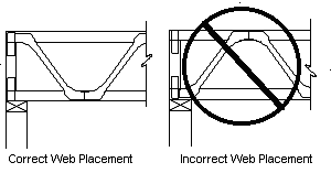
Care should be taken to place the Posi-STRUT truss the right way up. The Posi-STRUT web is always plated on the top chord directly over support points.
Non-load Bearing Walls
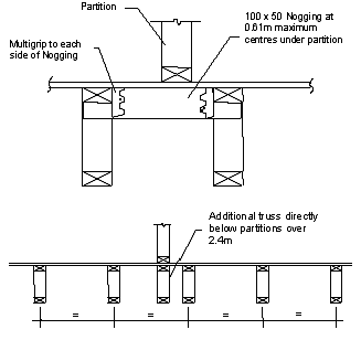
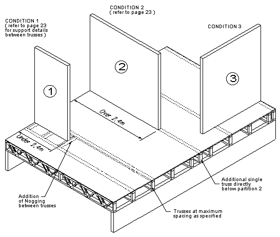
The placing of non-load bearing partitions on floor truss systems may necessitate additional stiffening of the structure. There are three situations:
1. If the length of the partition parallel to the trusses does not exceed 2.4 metres, no additional truss support is required. If the partition falls in between two trusses, noggings are required at 610mm centres (at truss web points) to stiffen the flooring.
2. Where the length of the partition exceeds 2.4 metres, an additional truss is required below the partition.
3. Generally for partitions placed perpendicular to the trusses, no additional support is required.
Load Bearing Walls
Posi-STRUT trusses supporting load bearing walls require special design by MiTek New Zealand Ltd.
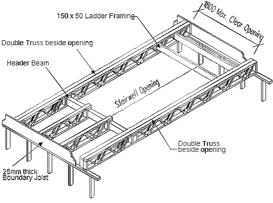
Stairwell Openings
Where openings are required on the upper floor for access due to stairways, it is possible to stop one or more trusses short and support them on headers fixed to adjacent trusses.
Provided not more than two trusses are stopped short, the adjacent trusses can be double trusses and the connection of the header to the double truss is as shown.
The recommended header beam size using either solid timber or GANGLAM beam can be obtained from Table 9 in the GANGLAM Selection manual.
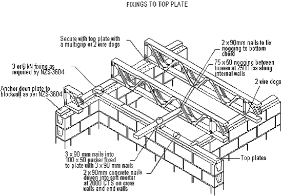
Fixings and Connections
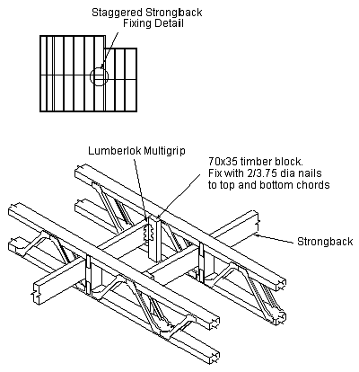
Strongbacks Selection & Detailing
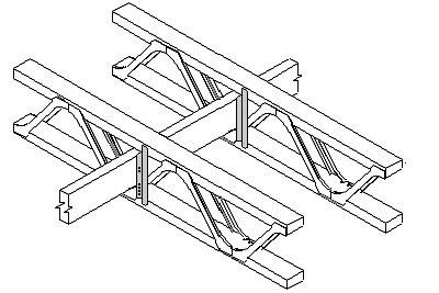
Strongbacks are required for floor trusses, but can be used for rafters and purlins. They are continuous members fixed to each truss and their primary function is much the same as solid blocking or herringbone strutting, which is to provide load sharing thereby increasing strength and rigidity, and restricting vibration of the floor.
Strongbacks should be placed at right angles to the truss just below the top chord at 2.5m maximum centres in positions as symmetrical as possible between supports. They should also be continuous from sidewall to sidewall. If splicing is necessary, follow the recommended detail shown.
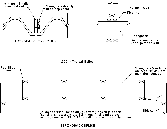
The recommended sizes of strongbacks are as the following table. We recommend that strongbacks are clamped to the top chord and fixed to vertical webs with 3 x 3.75mm dia nails. At the end of buildings they should be braced back to top and bottom chords with diagonal strutting as shown or with solid blocking.
Posi-STRUT Size Recommended Strongback Size PS20 90x45 PS25 140x45 PS30 140x45 PS40 190x45
Note these are the recommended sizes only, larger strongbacks can be used for prestige floors subject to sufficient depth between the chords of the truss.
Using Posi-STRUT Back Braces
1. The Back Brace allows quick and easy fixing of strongbacks to Posi-STRUT trusses without the need for timber vertical webs. The Back Brace also allows a degree of flexibility in the positioning of strongbacks as they do not need to be placed at truss panel points. This enables small variations in span to be accommodated without changing jig settings or strongback locations.
2. Insert strongbacks through trusses in accordance with the floor plan provided by Posi-STRUT truss designer. Ensure that the strongbacks are no greater than 2.5 metres spacing from supports or other strongbacks. Select where possible an opening in the truss which allows the strongback to rest on the bottom chord away from the Posi-STRUT web tooth cluster.
3. Place the Back Brace in position so that the leg with multiple holes is against the strongback and the vertical position is such that the screw holes in the leg against the Posi-STRUT truss are close to the centres of the timber chords. Fix bottom of Back Brace to bottom chord with 1 screw while maintaining strongback location.
4. Fix Back Brace to strongback with 2 screws, selecting a pre-punched hole which is approximately 30mm from the top and bottom edges of the strongback.
5. Fix Back Brace to top chord with 1 screw through hole provided.
Note: Do not over tighten the screws.
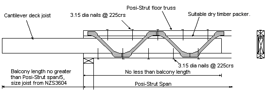
Cantilevers for Decks
These two details for a cantilevered deck fixed to a Posi-STRUT floor allow for a step down to the deck and the Posi-STRUT is protected from the weather.